Create objects from CSV, XYH, TXT files |


|
|
This mode is designed to create objects on a map based on information from delimited text files. The structure of the source file is defined such that one line in the file corresponds to one spatial object. Source files can have various extensions (TXT, CSV, XYH, etc.), with the primary requirement being the presence of delimiters between informational fields in a line. The program can be used for loading coordinates obtained from field surveys with geodetic equipment.
Source data in the file must be represented by a single line, including either: • Measurements of a single picket point in XYH format; • Measurements of a single object with a general coordinate description in WKT format.
To launch the data loading procedure in the mode dialog: 1. Select the source data file(s). 2. Configure the information line format. 3. Specify the name of the map where the data will be placed. 4. Configure the appearance of the objects to be placed on the map. 5. Click the Execute button.
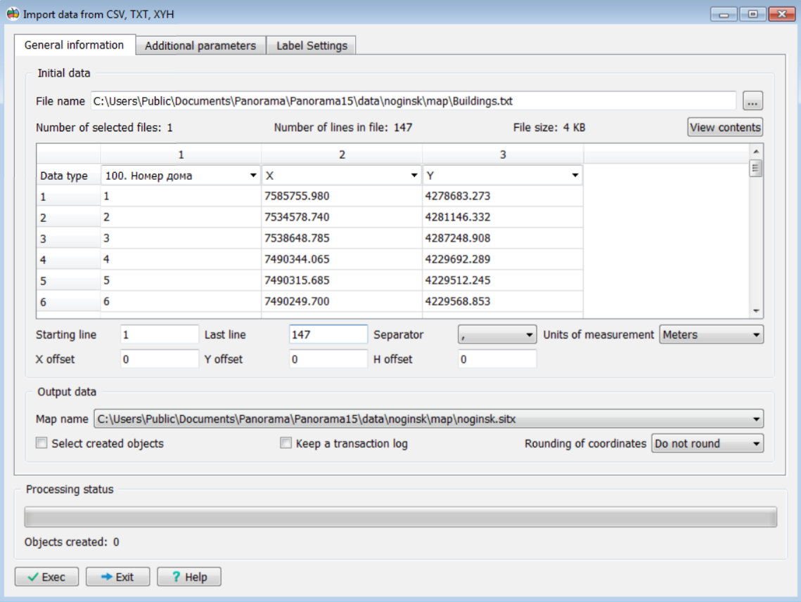
The General information tab contains elements for selecting source data, previewing the contents of the files to be loaded, and configuring the information line format.
General information tab
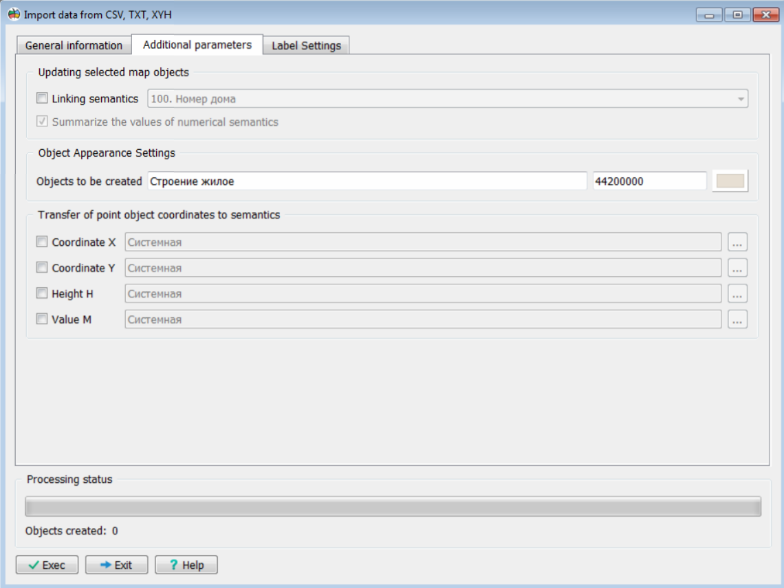
On the Additional Parameters tab, you can enable the update mode instead of the object creation mode by checking the Linking semantic box and specifying the semantic attribute. This semantic will be used to link rows from the file to objects on the map. If multiple file rows correspond to map objects, checking the Summarize the values of numerical semantics box will allow writing the sum of the values into the semantic; otherwise, the value from the last matching row will be written. For non-numeric semantics, the value from the last row is always written. This tab also allows configuration of the appearance of created objects and the semantics for transferring coordinate values.
Additional parameters tab
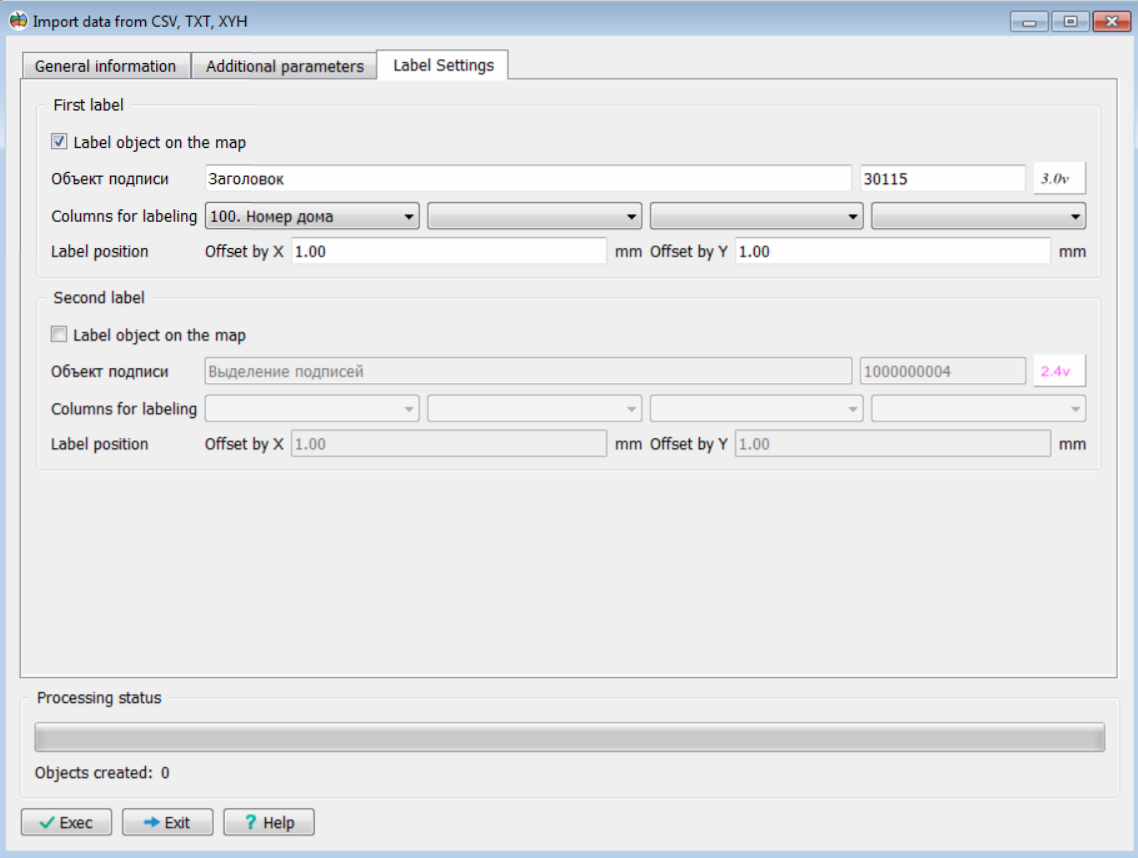
The Label Settings tab is used to configure labels for created or updated point objects. You can create two separate combined labels next to the object. Each label can contain up to 4 field values, selected by the user, arranged in multiple lines. For example, the first line could display the point height, and the second line its name, point number, or another field. The dialog allows you to specify the columns from the source file whose values will be used for labeling the points. For each label, individual vertical and horizontal offset parameters can be set, allowing placement anywhere relative to the main object.
Label settings tab
As source data, one or more text files with the same format of information line can be specified. One file may contain information of the following types:
To view and analyze the contents of the source file, its contents are displayed in a multi-line screen element designed to help determine how to process the data from the source file. The first fifty lines of the file are shown in this element. The first line is intended for configuring the composition of imported data. If a set of files is selected, information from the first selected file is displayed in the first line.
The number of columns (information fields) is determined automatically based on the number of delimiters in the source file. A dropdown list is provided for each column to configure the assignment of information fields, including:
Configuring the Assignment of Information Fields in the Source File
When configuring the format of the information line, the following should be considered:
The WKT (Well-Known Text) format is a text markup language for representing the vector geometry of objects on a map. The WKT format is defined in the ISO/IEC 13249-3:2016 standard "Information technology – Database languages – SQL multimedia and application packages – Part 3: Spatial" (SQL/MM) and in ISO 19162:2015, "Geographic information – Well-known text representation of coordinate reference systems." Below are the types of objects and their corresponding representation with metrics in the WKT format.
Types of Objects and Their Corresponding Representation with Metrics in WKT Format
When processing MULTIPOINT, MULTILINESTRING, and MULTIPOLYGON objects, the corresponding number of objects of the specified localization will be plotted on the map and grouped into a set of objects.
As a result of processing the source files, the following combinations of objects may be plotted on the map:
— point objects according to the number of rows in the source file; — linear objects according to the number of source files; — area objects according to the number of source files;
— objects of different localizations and types.
When processing source data in the XYH format, the localization of the object and its appearance are determined by the settings in the Appearance of Created Objects tab. At the same time, only point, only line, or only area objects can be created. When processing source data in the WKT format, the localization of the object is determined by the content of the WKT field. The appearance of the object is determined by the value of the object key field. If there is no value for the object key, then it is determined by the settings specified in the Appearance of Created Objects tab.
Additional settings in the dialog provide for:
The import process begins after clicking the Execute button. |