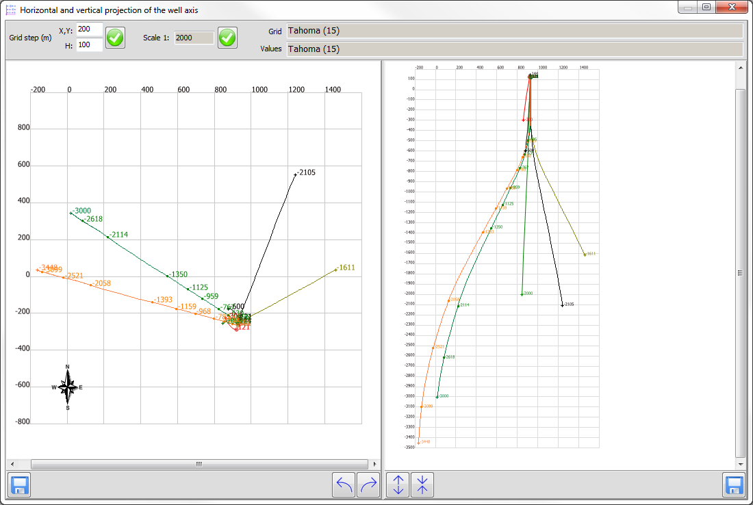
Horizontal and vertical projection of the well axis |


|
|
Prior to the execution of the regime, the following must be mapped: the wellhead, the bottom of the well, the wellbore axis, and the intersection points of the layers. To start the mode, select one or several linear objects on the map that describe the axis of the wellbore and press the mode button.
Building images of horizontal and vertical projections of well is performed in a conventional coordinate system. In this case, the direction of the Y axis is calculated so that at the first drawing the image of a horizontal projection its horizontal dimensions were maximum. The centre of dimensions of the image of a horizontal projection is taken as the origin of coordinates. In addition to the axis of the wellbore, when constructing the inclinogram, the wellhead and bottom of each well and the intersection points of the layers (code 1583) available on the map are used. To search for the intersection points of the layers, the value of the semantic characteristic the well number (code 882) is used. Improving the clarity of the images of the horizontal and vertical inclinogram schemes can be achieved by adjusting the following parameters: - Grid step (m) on X, Y and H; - Scale 1: (of the scheme); - Fonts for formation of titles of a coordinate grid and values on point objects of projections images. To increase the clarity and analysis of the inclinogram images, it is possible to rotate the projection plane of the profile, which defines the coordinate system of the scheme, as well as to compress and stretch the image on the vertical profile along the vertical axis. The formed images of schemes (separately) can be saved as maps in the SITX format for execution of their additional refinement and design by means of the Map Editor, or in the form of images in JPG, PNG and TIF formats.
|
 The mode is intended for building an inclinogram, including a well plan in horizontal projection and a profile of the well axis in a vertical projection.
