Editing of a mark |


|
|
The three-dimensional mark consists of nodes, each of which has its own description. The following kinds of nodes are supported: - Box; - Sphere; - Horizontal cylinder; - Vertical cylinder; - Stereoscopic picture; - Vertical plane; - Horizontal plane; - Triangular horizontal prism.
To each description the elements belong, surface of which is drawn with help of color or of texture preset in the description.
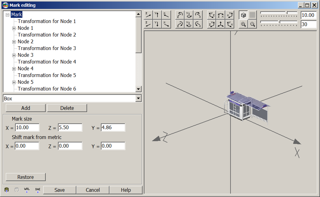
In the top left corner the user sees a tree of a mark. Corresponding Parameters are shown at the left below. For editing parameters of a mark or node it is necessary to choose in a tree a corresponding line. After input of data, before transition to other line of a tree, you must memorize them (Save button). At only created mark the nodes are not present. For creation of a new node choose in the drop-down list of nodes a suitable one and press Add button. For editing parameters of node establish the cursor onto the necessary node. The marked node can be rotated or be shifted concerning the rest of mark by means of toolbars: Turn and Rotation. At that it is possible and to move and to rotate with the preset step (Fields of input on the right below). If the node is marked, in a window of displaying it is highlighted by a grid. Rotation for all mark is only for viewing. The View toolbar allows to see and to edit nodes of a mark at the view from above, in front view and on the right-side view. At creation of node it contains the standard description. For editing the description of node in dialog for input of the sizes and descriptions of a mark the Design bookmark is used. To each node of a mark one picture corresponds. By double click onto the image the user gets into Editing of description dialog. In the Mark editing dialog, you can copy a mark from the template to the template via the clipboard (copy to buffer - A mark as a template used in creating a three-dimensional view of point, vector, line, and polygon objects can be not only created with using the Editor of 3D mark, but also imported from a VRML format file created using third-party programs. When importing, the following nodes types are loaded: - parallelepiped; - sphere; - cylinder; - cone; - surface specified by coordinates array (FaseSet); - array of points (PointSet); - array of lines (LineSet); - grid of heights (Grid); - extrusion (Extrusion).
VRML-format file of version 2.0 or higher can be downloaded into a mark. Simultaneously, when loading a mark, textures from BMP and JPEG are loaded. Nodes and events related to animation, as well as prototypes of nodes (PROTO and EXTERNPROTO) in this version are not loaded. Editing of marks downloaded from VRML, for the present is limited to the following functions: change of the mark size, change of binding the mark relative to the object metrics, change of the position and size of individual nodes, change of design of individual nodes. It is possible to edit the geometry of the nodes, except for nodes of the type: point set, line set, grid, extrusion. Nodes that include surfaces defined by an array of coordinates can be changed in the Editing an array of polygons dialog.
|